What a Chipbreaker Actually Does
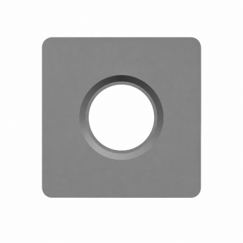
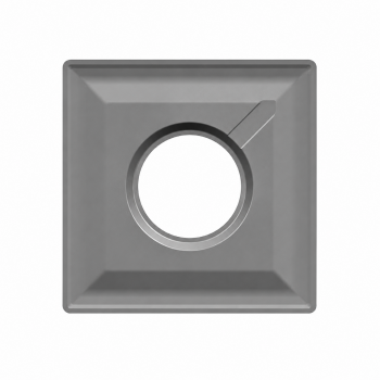
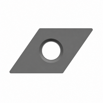
A chipbreaker is the formed or ground geometry behind the cutting edge of an insert. It influences how the chip flows, curls, contacts the rake face and eventually separates. Its purpose is not simply to create the shortest possible chip. The practical objective is to produce chips that are predictable, safe, easy to evacuate and unlikely to damage the workpiece or tool.
Long continuous chips can wrap around the component or tool, scratch finished surfaces and stop automated production. Excessively small and hard fragments, however, may indicate that the chip is being restrained too strongly, increasing edge load and fracture risk. The goal is therefore controlled chip formation—not maximum fragmentation.
Chipbreaker, Edge Preparation and Grade Are Different
| Element | Primary role |
|---|---|
| Chipbreaker | Controls chip flow, curl and chip-contact behavior. |
| Edge preparation | Controls cutting-edge sharpness and strength. |
| Carbide grade | Combines the substrate, coating system and applicable post-treatment. |
These elements must work together. A roughing geometry used at a very small finishing allowance may rub rather than cut cleanly, while a sharp finishing geometry can chip under a heavy interrupted load.
The Three Primary Selection Factors
1. Machining area
Classify the operation as finishing, medium machining or roughing. This establishes the required balance between sharpness, chip control and edge strength.
2. Workpiece material
Chip behavior changes substantially across ISO P steel, M stainless steel, K cast iron, N non-ferrous materials, S heat-resistant alloys and titanium, and H hardened materials. A geometry intended for steel should not automatically be assumed suitable for stainless steel or aluminum, even if it fits the same insert pocket.
3. Actual feed and depth of cut
Every chipbreaker has an effective application window based mainly on feed per revolution (f) and depth of cut (ap). Select from the manufacturer’s ap × f map. The operation name alone is insufficient: a pass called finishing may actually run in a medium-machining range, while an extremely small allowance may fall below the effective range of a finishing geometry.
Finishing, Medium and Roughing Comparison
| Selection factor | Finishing | Medium | Roughing |
|---|---|---|---|
| Feed and depth of cut | Low and shallow | Medium range | High and deep |
| Edge condition | Sharp, low resistance | Balanced | Reinforced |
| Edge strength | Lower | Medium | High |
| Surface-quality potential | High | Good | Secondary consideration |
| Chip-control range | Optimized for thin chips | Broad and versatile | Optimized for thick chips |
| Typical role | Finishing and light cuts | General first choice | Heavy and interrupted cuts |
A medium geometry is often a sensible starting point for mixed or general production because it covers a broader range. It should not replace a dedicated finishing or roughing geometry when the application clearly falls outside that range.
Conceptual Chipbreaker Map
This directional map explains the selection logic; it is not a numerical specification for any product.
| Depth / Feed | Low feed | Medium feed | High feed |
|---|---|---|---|
| Shallow depth | Finishing | Finishing / medium overlap | Product-dependent |
| Medium depth | Finishing / medium overlap | Medium | Medium / roughing overlap |
| Deep depth | Product-dependent | Medium / roughing overlap | Roughing |
Material-Specific Selection Direction
| ISO group | Typical chip behavior | Initial direction | Key risk |
|---|---|---|---|
| P Steel | Usually controllable; low-carbon steel can be ductile and adhesive | General-purpose P geometry; sharper option for low-carbon steel | Long chips and built-up edge |
| M Stainless steel | Long, tough chips and work hardening | Sharp positive M geometry with controlled curl | Work hardening, notch wear and chip hammering |
| K Cast iron | Gray iron normally self-breaks; nodular iron may be more continuous | Strong K geometry; chipbreaking may be secondary to wear resistance | Abrasion and chipping |
| N Non-ferrous | Ductile, adhesive and often continuous | Highly positive, sharp and often polished geometry | Built-up edge and adhesion |
| S HRSA / titanium | Tough chips, high heat and difficult evacuation | Sharp material-specific geometry with adequate support | Notch wear, heat and edge failure |
| H Hardened material | Often shorter chips; high edge load | Strong edge; prioritize grade and edge preparation | Chipping and rapid wear |
Variables That Change Chipbreaker Performance
Selection cannot be completed with ap and f alone. Also evaluate cutting speed, nose radius, insert shape, approach angle, toolholder orientation, external/internal/face turning, overhang, rigidity, coolant direction and pressure, interruption, hardness and heat-treatment condition. Feed strongly influences chip thickness, while depth of cut strongly influences chip width; the other variables then change how the chip curls and separates.
Troubleshooting Guide
| Observed problem | Possible cause | Corrective direction |
|---|---|---|
| Long continuous chips | Feed or depth below the effective range | Check the application map; adjust safely or select a light-cut geometry. |
| Very small, hard fragments | Chip restrained too strongly | Evaluate a more open geometry or reduce feed within its range. |
| Edge chipping | Geometry too sharp, interruption, vibration or chip hammering | Improve rigidity and consider a stronger geometry, tougher grade or reinforced edge. |
| Poor finish in a light cut | Roughing geometry rubbing | Use a sharper finishing geometry and confirm minimum depth of cut. |
| Built-up edge | Adhesive material, unsuitable geometry or speed | Use a sharper material-specific geometry and review speed and coolant. |
| Good chips but short tool life | Excessive edge load or wrong grade | Keep the geometry but review grade and cutting parameters. |
| Poor internal-turning evacuation | Restricted space, overhang or wrong chip direction | Use an internal geometry and review coolant delivery and holder stability. |
Important: parameter changes must remain within machine, workholding, insert and manufacturer limits. “Increase the feed” is not a universal solution.
JetEdge Chipbreaker Naming
JetEdge chipbreaker codes are the official designations used on product pages, quotations, packaging, technical documents and purchase orders. JetEdge codes remain the primary product identity.
JetEdge official code: MGM — secondary wording: “M2-type application reference”
JetEdge official code: MRA — secondary wording: “DL-type application reference”
Market-reference terms are included only to help customers recognize a general application direction. They do not claim identical geometry, dimensions or performance, and do not indicate affiliation with another manufacturer. Compatibility must be confirmed from the complete insert designation, drawing, dimensions and cutting conditions.
Recommended Selection Workflow
Exact alloy and hardness
External, internal, face or profile
Finishing, medium or roughing
Feed, depth, speed and interruption
Chipbreaker, grade and edge
Check chips, finish and wear
Information to Send JetEdge
- Current insert and toolholder designations
- Workpiece material and hardness
- External, internal, face or profile operation
- Finishing, medium or roughing operation
- Cutting speed, feed per revolution and depth of cut
- Nose radius and interruption level
- Coolant method
- Current chip-control or wear problem
Technical References
- Tungaloy, Basics of Chipbreakers—From Fundamental Theory to Selection.
- Tungaloy User’s Guide—Factors Affecting Chip Control.
- Sandvik Coromant—Finishing, Medium and Roughing Turning Geometries.
- Yılmaz, Karabulut and Güllü, A Review of Chip-Breaking Methods for Continuous Chips in Turning.
- Shinozuka et al., A Chip-Breaking System for Mild Steel in Turning.
- Pacella et al., A New Low-Feed Chip-Breaking Tool and Its Effect on Chip Morphology.